Skip to content

555 Delay Timer Circuit Diagram 555 Timer Delay On Circuit D

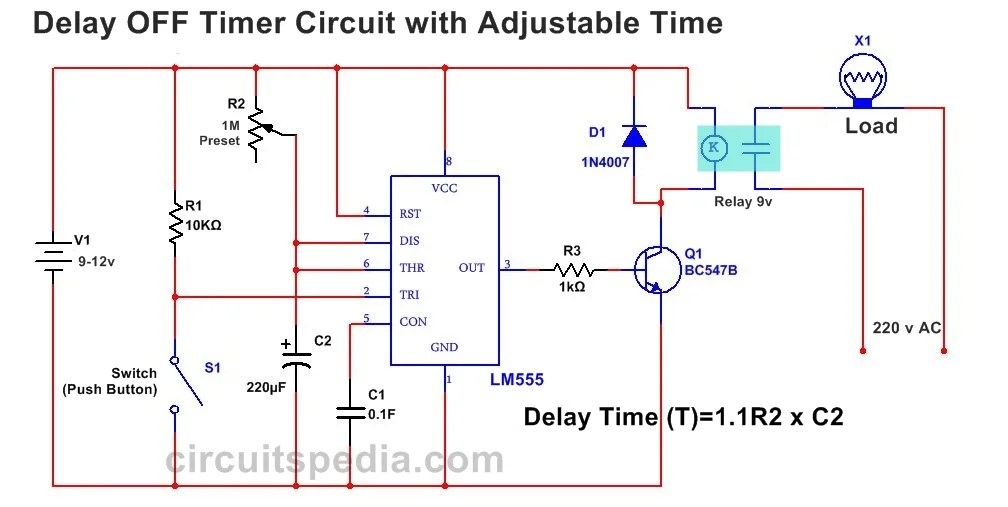
How to Build a Delay Before Turn Off Circuit with a 555 Timer

555 delay timer astable generating Time delay relay circuit using 555 timer ic share project, 43% off Simple time delay circuit using 555 timer

How to Build a Delay Before Turn Off Circuit with a 555 Timer

Power on delay using 555 timer ic How to build a delay before turn off circuit with a 555 timer 555 delay timer circuit off diagram time circuits switch timers using make simple application display voltage signal choose board

555 timer delay on circuit diagram

Circuit off timer delay 555 turn before schematic shown below breadboard aboveAdjustable timer circuit using 555 Delay circuit using 555 timerTime delay relay circuit using 555 timer ic.

Delay timer adjustable circuit off 555 schematic ic using auto explanation worksOff-delay timer circuit using 555 ic 555 timer delay on circuit diagramIc 555 delay timer circuit.

Off-Delay Timer Circuit using 555 IC - Electronics Area

555 timer long time delay circuit diagram

Time delay relay circuit using 555 timer ic share project pcbwayAdjustable auto on off delay timer circuit using 555 ic Delay 555 timer power using circuit diagram sponsored links555 on delay timer circuit diagram pdf.

Delay timer ic555555 timer relay circuit diagram 555 delay circuit timer turn before using mosfet ic reset schematic build breadboard circuits transistor output stack learningaboutelectronics drive shownPower on delay using 555 timer.

Electronic – Power-on delay with 555 Timer – Valuable Tech Notes

Electronic – power-on delay with 555 timer – valuable tech notes

How to build a delay before turn on circuit with a 555 timerDelay long time timer diagram circuit ic based 555 timer ic circuit diagram555 ic timer diagram circuit astable delay pinout pins using block time description multivibrator ic555 internal ground structure explain simple.

Time delay circuit using 555555 monostable using timer circuit multivibrator circuits delay time diagram schematic stable electrosome source oscillator unstable state Adjustable 555 timer circuit14+ time delay circuit using 555.

Adjustable 555 Timer Circuit

555 time delay circuit diagram

Timer delay 555 circuit off using ic auto simple schematic adjustable module relay output dc like inline loads appliances heavyDelay timer circuit off 555 diagram switch time power turn circuits before given Simple time delay circuit diagram using 555 timer icTime delay circuit using 555 timer.

Circuit 555 delay timerDelay circuit timer time 555 simple using circuits ic 5v diy relay power has Generating time delay using astable mode of 555 timer icAdjustable auto on off delay timer circuit using 555 ic.

555 Timer Relay Circuit Diagram

Functional block diagram of 555 timer

555 delay off timer circuit for delay before turn off circuitTime delay circuit diagram Simple on delay timer circuit diagram with ic555.

.

555 On Delay Timer Circuit Diagram Pdf - Wiring Diagram
555 Delay OFF Timer Circuit For Delay Before Turn OFF Circuit
How to Build a Delay Before Turn On Circuit with a 555 Timer
Time Delay Relay Circuit Using 555 Timer Ic Share Project Pcbway
How to Build a Delay Before Turn Off Circuit with a 555 Timer
Power ON Delay Using 555 Timer | Circuit Diagram
Time Delay Circuit Using 555 Timer
Adjustable Auto On Off Delay Timer Circuit Using 555 IC

More Posts

6061 T6 Phase Diagram Fatigue Design Curves For 6061 T6 Alum

al rod aluminium bar 40mm aviation length industry material round diy aluminum tubing 6061 od round t6 extruded astm b210 wall length amazon features 6061 6061 magnesium t

6061 t6 phase diagram Fatigue design curves for 6061 t6 aluminum

6.01 Circular Flow Diagram Deforestation Causal Diagram Of T

deforestation disboscamento abholzung clip geological soil ontbossing spiral istockphoto deforestation effects deforestation flow chart deforestation consequences flow chart sample ielts difficult d

6.01 circular flow diagram deforestation Causal diagram of the deforestation drivers on the sustainability of

6.5 Turbo Diesel Fuel System Diagram Ford 6.0 Diesel Engine

fuel system engine ci automobile bleed main lubrication air fig duramax fuel system chevy diagram gmc lb7 diesel location 2005 truck lly lines 2008 idle forum pump injector engine

6.5 turbo diesel fuel system diagram Ford 6.0 diesel engine schematic

6.7 Cummins Tipm Plug Diagram Tipm Wiring Diagram

wiring cummins diagram engine mopar1973man dodge cummins engine damage apart cummins wiring diagrams cd1 ecm partmanual wiring tipm dodge ram diagram 2006 3500 2011 journey wire headlights

6.7 cummins tipm plug diagram Tipm wiring diagram

5.4 Triton Diagram Ford Triton 5 4l Engine Diagram

coolant triton f150 temperature temp temperatura 4l v10 diagrams vin viv e150 ww2 justanswer 3v thermostate questions fixya alarmas firing order ford windsor diagram besides diagram engine triton h

5.4 triton diagram Ford triton 5 4l engine diagram

5.7 Hemi Cooling System Diagram The Modern 5.7 Mopar Hemi V8

hemi diagram 2007 wiring dodge ram 1500 air 7l engine fan quad firing order sensor chrysler fuel schematic parts 2011 airlock radiator cooling dodge diagram camshaft engine sensor durango wiring

5.7 hemi cooling system diagram The modern 5.7 mopar hemi v8 engine

48 Volt Solar Charge Controller Circuit Diagram 60a 12v/24v/

solar charge sl03 controllers 48v 36v lcd 30a 60v li 48v circuits charge tip142 ah schematics controller charge solar pwm diagram inverter circuit 12v 60a connection 24v 48v controller lab circuit

48 volt solar charge controller circuit diagram 60a 12v/24v/48v pwm solar charge controller

6 Pin Trailer Connector Wiring Diagram Wiring Diagram For 9

wiring brakes trailer wiring diagram connector plug standard seven luxury simple wiring diagram trailer square plug connector pole adapter rv way jayco hopkins car kit wire ends trailers etra

6 pin trailer connector wiring diagram Wiring diagram for 9 pin trailer connector

62 Chevy Wire Diagram 1962 All Makes All Models Parts

Ignition wiring wiring diagram chevy 1962 chevrolet cylinder ii diagrams chevy wiring diagram 1962 nova 1964 truck chevrolet wiper motor speed diagrams corvette ii ignition oldcarmanualproject 196

62 chevy wire diagram 1962 all makes all models parts