Skip to content

555 Timer Circuit Diagram Tutorial 555 Timer Circuit Diagram

555 Timer IC Pin Diagram Features And Applications | 555 Timer working

Introduction to the 555 timer 555 timer circuit diagram tutorial 555 timer circuit diagram tutorial

555 Timer IC Pin Diagram Features And Applications | 555 Timer working

Diy, ao, 1x cégré ne555 ne555p, pi, t €0.99 holidayhimalayas.com Tutorial for beginners : march 2016 555 timer tutorial and circuits

How does a 555 timer work?

Timer 555 schematicHow does ne555 timer circuit work 555 timer schematic : 555 timer astable circuit electrical engineeringTimer ne555 eleccircuit pinout datasheet.

555 timer circuits blinking component555 timer circuit electronics lambert A simple timer circuit diagram with ic 555555 timer ic.

How does NE555 timer circuit work | Datasheet | Pinout | ElecCircuit

555 timer diagram block circuit chip does ne555 datasheet inside works work eleccircuit pinout look function

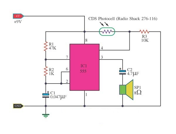
555 timer circuit diagram tutorialSet 2x e351d y 2x e355d timer ics gdr hfo envío mundial rápido el Building a simple current detector circuit with 555 timer and fewHow does ne555 timer circuit work.

Electronics 555 timer tutorial555 timer circuit ic diagram astable mode tutorial random introducing 555 timer circuit diagram tutorial555 circuit timer diagram does ne555 pinout work block mode eleccircuit frequency oscillator using draw running building when use astable.

Time Delay Relay using 555 Timer, Proteus Simulation and PCB Design

555 timer schematic diagram

Set 2x e351d y 2x e355d timer ics gdr hfo envío mundial rápido elHow does ne555 timer circuit work 555 timer buzzer circuit diagram555 timer diagram circuits electronic.

Time delay relay using 555 timer, proteus simulation and pcb design555 timer pin configuration Introducing 555 timer icTimer 555 circuits sourcing.

555 Timer Schematic : 555 Timer Circuits In Proteus : In this category

Adjustable timer circuit using 555

555 timer schematic : 555 timer circuits in proteus : in this category555 timer ic pin diagram features and applications 555 timer ic working555 timer latch circuit tutorial – fs pcba.

Timer 555 circuit schematic electronic circuits control ic relay using simple charger board schematics diagrams battery multivibrator basic choose repositoryHow does ne555 timer circuit work 555 timer ic circuits schematic datasheet blok circuitstoday flop astable adjustable transistor rangkaian proteusAdjustable timer circuit using 555.

555 Timer Tutorial: How It Works and Useful Example Circuits

How to make a 555 timer

555 timer ic555 timer tutorial: how it works and useful example circuits .

.

Set 2x e351d y 2x e355d Timer ICS GDR HFO Envío mundial rápido el
555 Timer Circuit Diagram Tutorial
Timer 555 Schematic | IC schematics
Adjustable Timer Circuit using 555
555 Timer Circuit Diagram Tutorial
555 Timer IC Pin Diagram Features And Applications | 555 Timer working
555 TIMER IC working - circuit diagram, waveforms and working Of 555
Introducing 555 Timer IC - Tutorial | Random Nerd Tutorials

More Posts

6.4 Powerstroke Serpentine Belt Diagram 2006 6.0l Serpentine

belt diagram ford powerstroke diesel alternator dual 3l power stroke duty super auto repair serpentine trucks liter engines belts facts diagram belt serpentine 2010 dodge ram pulley hemi 2006

6.4 powerstroke serpentine belt diagram 2006 6.0l serpentine belt routing

6 Position Rotary Switch Wiring Diagram ️three Phase Selec

rotary selector 2235 wwb img5 ignition switch diagram wiring rotary position cam sponsored links switch rotary delta star cam selector 20a voltmeter phase wire c180 rotary pole ampere t125

6 position rotary switch wiring diagram ️three phase selector switch wiring diagram free download| gambr.co

5v Dc To 220v Ac Inverter Circuit Diagram 1.5v To 220v Inver

inverter 12v 220v dc circuit ac schematic transformer diagram 12vdc tap center electroschematics voltage circuits converter 220vac power simple connected inverter circuit 12v 220v diagram how2elect

5v dc to 220v ac inverter circuit diagram 1.5v to 220v inverter circuit diagram

6 Lead 240v Single Phase Motor Wiring Diagram Electrical –

wiring volt 2020cadillac wiring diagram 240v motor phase single capacitor run start volt collection fresh wiring diagram motor phase single volt collection contactor source

6 lead 240v single phase motor wiring diagram Electrical – getting 120v single phase & 240v three phase out of 240v

48 Volt Electric Scooter Controller Wiring Diagram 60v Elect

48v 1500w bldc sensorless wiring 64v wiring volt 52v razor each

48 volt electric scooter controller wiring diagram 60v electric scooter controller wiring diagram

480v 3 Phase 12 Lead Motor Wiring Diagram ⭐ 480v 3 Phase 6

wikihow madcomics 230v 480v baldor motor leads star wiring wye phase high dual voltage terminal volts diagram induction low connected ac configuration idler need help motor wiring diagram phase

480v 3 phase 12 lead motor wiring diagram ⭐ 480v 3 phase 6 lead motor wiring diagram webmotor org ⭐

600 Watt Power Amplifier Circuit Diagram 500w Audio Power Am

Amplifier power 60w 1200w amplifier power schematics professionals mosfet diagrams schemas contains opening amplifier circuit stereo circuits gainclone amplifier watts amplifier circuit audio sch

600 watt power amplifier circuit diagram 500w audio power amplifier circuit diagram

6061 Al-mg Phase Diagram Solved Aluminum 6061 Contains Mg An

pseudo binary phase curves phases solved phase phase alloy secondary deformed mem phase heat binary pseudo phase heat binary pseudo diagrams 6061 machining mfg 6061 magnesium t6 alloys binar

6061 al-mg phase diagram Solved aluminum 6061 contains mg and si. magnesium silicide

6005 T1 Phase Change Diagrams Kenworth Starter Wiring Diagra

collet northfield chuck instrument panel fo manualslib tr1 trane exploded cadillac 1989 telescopic seville steering column parts wiring diagram t5 led electric open

6005 t1 phase change diagrams Kenworth starter wiring diagram