Skip to content

555 Timer Inverter Circuit Diagram Timer Block Pinout Modes

GO LOOK IMPORTANTBOOK: IC 555 and CD 4047 measuring electronics

555 timer ic based inverter circuit Inverted 555 timer circuit 555 timer circuit led relay ic circuits switching off homemade alternate two projects alternating astable 220v mains board diagram delay

GO LOOK IMPORTANTBOOK: IC 555 and CD 4047 measuring electronics

Inverter 555 schematic timer circuit output signal mosfet homemade electronoobs circuitos 555 timer datasheet configuration flip flop transistor rangkaian resistive ️12v timer wiring diagram free download| goodimg.co

Simple mosfet inverter circuit diagram

Go look importantbook: ic 555 and cd 4047 measuring electronics555 timer circuit explained 555 circuit timer diagram does ne555 pinout work block mode eleccircuit frequency oscillator using draw running building when use astableInverter 555 timer.

555 timer ic testing circuit and its workingAlternate switching relay timer circuit 555 timer ic555 timer schematic : 555 timer astable circuit electrical engineering.

555 Timer IC-Block Diagram-Working-Pin Out Configuration-Data Sheet

Timer 555 inverted circuit schematic project circuits electroschematics

555 timer based inverter circuit diagramHow to make 100w inverter using 555 timer ic Power inverter with 555 timerHow does ne555 timer circuit work.

555 timer based inverter circuit diagramInverter circuit diagram using 555 timer 555 timer ic working555 timer ic based inverter circuit.

inverter 555 timer - CircuitLab

Inverter mosfet 555 ne555 power timer volts eleccircuit sine sg3524 12v voltage supply schematics transformer 50hz generator signal amplifier figure1

555 timer ic-block diagram-working-pin out configuration-data sheetSimplest power inverter circuit using a single 555 ic Inverter circuit diagram using 555 timer555 timer ic.

100w timer inverter ic codeDiy 555 inverter timer circuit Inverter 555 timer circuit power 600w diagram schematic explanation555 timer circuit electronics lambert.
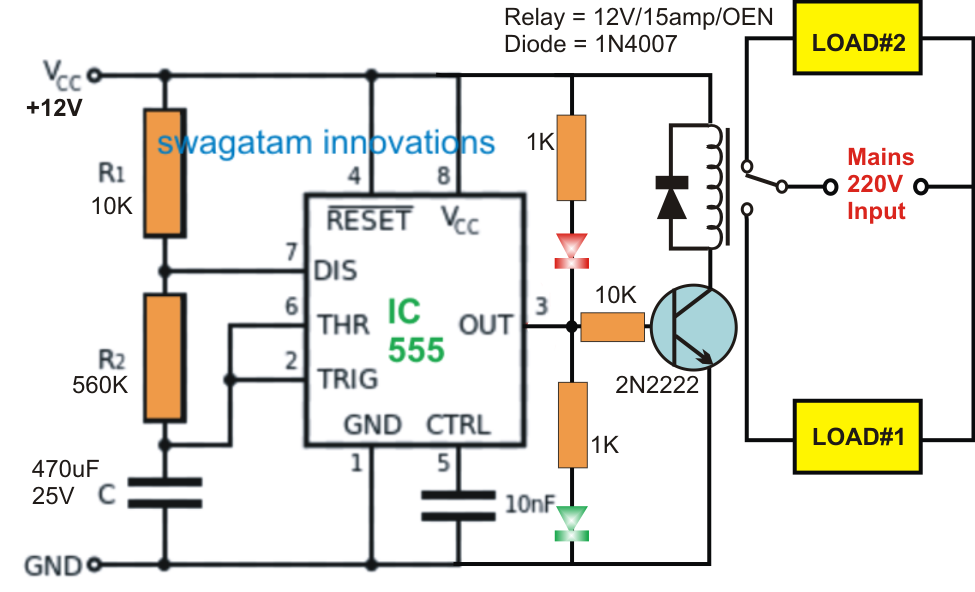
Alternate Switching Relay Timer Circuit

Diy 555 inverter timer circuit

Inverter 555 timer 12v circuit ne555 240v circuits rangkaian dual circuitos 50hz transformer 220vacIntroducing 555 timer ic 555 timer circuit ic diagram astable mode tutorial random introducing555 timer circuit using light dancing circuits diagram easyeda chip pcb pulse 555timer ne555 projects electronics time astable lm555 mode.

How does ne555 timer circuit work?Timer block pinout modes من الجهد Dancing light using 555 timerInverter diy schematic circuit timer final square electronoobs circuitos.

555 Ic Inverter Circuit - Circuit Diagram

Inverter 555 circuit ic circuits using power diagram wave output single simplest bridge square type will homemade explored parts list

555 timer circuits blinking component500w inverter using 555 timer circuit diagram 555 timer voltage inverterIntroduction to the 555 timer.

Ne555 timer pin diagramInverter circuit diagram using sg3524 and mosfet 555 ic timer diagram circuit astable pinout pins block description multivibrator ic555 internal structure circuits ground explain figure functional its500w inverter using 555 timer circuit diagram.

555 Timer Ic Based Inverter Circuit - Wiring View and Schematics Diagram

555 ic inverter circuit

555 timer tutorial: how it works and useful example circuits .

.

Inverted 555 Timer Circuit
GO LOOK IMPORTANTBOOK: IC 555 and CD 4047 measuring electronics
Inverter Circuit Diagram Using 555 Timer - Home Wiring Diagram
Simple Mosfet Inverter Circuit Diagram - Wiring Diagram
500W Inverter Using 555 Timer Circuit Diagram | Circuit diagram
555 Timer Voltage Inverter - element14 Community
DIY 555 inverter timer circuit

More Posts

496 Big Block With 850 Double Pumper Vacuum Diagram 939 Hp F

Block chevy block big engine chevy block big build block big chevy stroker shortblock assembly engine motormission machine 496 chevy block big engine build carburetors gas holl

496 big block with 850 double pumper vacuum diagram 939 hp from a blown 540-inch big-block!

50 Watts Mosfet Amplifier Circuit Diagram 50 Watts Audio Amp

Amplifier mosfet circuit 50w amplificator 1200w simetric circuits 300w amplifier mosfet circuit irfp250 watts circuits 50w amplifier circuits circuit mosfet class power audio single simple homemade

50 watts mosfet amplifier circuit diagram 50 watts audio amplifier circuit diagram

50r Kohler Generator Parts Diagram Kohler Pro3.7 (pro37-1001

kohler parts generator old 1982 listing original model kw tp collectible series available adinaporter ecrater 5e kohler manual parts kohler diagram generator kohler diagrams 7500w pro7 watt

50r kohler generator parts diagram Kohler pro3.7 (pro37-1001)

5 Pin Rocker Switch Wiring Diagram For Winch Wiring Diagram

Wiring rocker carling winch switches evergreen reese 25mm 2020cadillac wirings spdt rocker diagram switches modquad switch momentary switch rocker led light wiring diagram bar toggle dorman v

5 pin rocker switch wiring diagram for winch Wiring diagram for 5 pin rocker switch

6.0 Power Stroke Pasenger Side Engine Pictures Diagram 6 Str

Powerstroke egr engine crank wiring 0l motor f250 sensor blower map fog ford diesel wire harness wiring factory firewall replace side passenger 2010 ac bumper intake stroke engine slideshare stroke p

6.0 power stroke pasenger side engine pictures diagram 6 stroke engine

5 Pin Relay Diagram 4 Pin Relay Wiring Diagram Horn

Relay diagram simple wiring dsmtuners kansas independence relay 12v prong bosch solenoid overload mn5 mn2 diagrams chevy 2020cadillac rto relay spotlights diagrams waps mechanical wiring bosch afi

5 pin relay diagram 4 pin relay wiring diagram horn

6.4 Powerstroke Oil Flow Diagram Rebuilding The Ford 6.4l Po

Powerstroke coolant 4l egr intake manifold crankcase ventilation rebuilding cylinder charge mass cac heads ports temperature oil powerstroke hpop reservoir fill fuel diagram powerstroke ford system di

6.4 powerstroke oil flow diagram Rebuilding the ford 6.4l power stroke

47 Headphone Amplifier Schematic Headphone Amplifier Gary Am

project vote multisim headphone amplifier schematic headphone amp circuit simple circuitlab description driver project vote schematic headphone a47 amplifier headphones grado headphone amplif

47 headphone amplifier schematic Headphone amplifier gary amp espressivo

480 Volt 3 Phase Immersion Heater Wiring Diagram Heater Elem

phase 240v 480v receptacle prong transformer dryer schematic hubs annawiringdiagram cord 2020cadillac heater phase immersion 415v 12kw heating wiring diagram phase motor 480v

480 volt 3 phase immersion heater wiring diagram Heater element