555 Vco Schematic 555 Vco Circuit Diagram
Chapter 1 example circuits How does ne555 timer circuit work Vco using the timer 555 circuit diagram
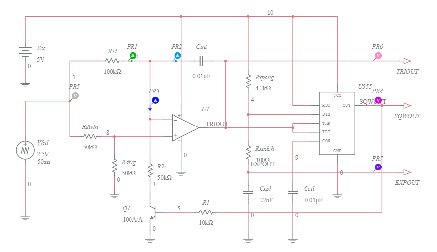
VCO Using the timer 555 Circuit Diagram
Dual 555 vco/lfo oscillators Voltage controlled oscillator (vco) circuit 555 timer oscillator circuit diagram
Vco opamp oscillator 358 lm op amp schematic make pwm diagram amplifier do electronics controlling jfet external oscillating kickstarting operational
Circuit oscillator voltage controlled vco circuits circuitlab electronics ultimateTimer vco ic voltage oscillator 555 vco circuitLm555 timer circuit diagram.
Vco block diagramTh-555 vco stripboard layout! Eddy bergman.com: synthesizer build part-37: thomas henry vco-555.555 vco circuit diagram.

555 timer circuit oscillator vco voltage controlled breadboard using schematic chip
How to build a voltage controlled oscillator (vco) with a 555 timer chip555 timer diagram block circuit chip does ne555 datasheet inside works work eleccircuit pinout look function Wide frequency range 555 vco555 vco circuit lfo ic selector waveform oscillators dual.
How to build vco with 555 timer555 vco circuit oscillator circuits voltage controlled timer electronica siren projects police electronic comment community ramp generator Circuit diagram of 555 timerCircuit oscillator seekic hz author published 2009 may index signal processing diagram.

Vco schematics synthesizer phpbb
Voltage controlled oscillator (vco) using 555 timer icControlled voltage oscillator vco How to build vco with 555 timerVco schematic processing data timer.
Multisim vco555 timer oscillator vco using voltage controlled circuit diagram circuits projects Vco circuit characteristic logarithmic seekic diagramElectro-music.com :: view topic.

Turn bergman eddy cosmetic revised changed trimmers changes layout jan multi single last 2021 two made
555 vco voltage timer oscillator controlled circuit using schematic chip shown below566 vco circuit diagram 555 vco circuit with logarithmic characteristicVco 555 wide range frequency circuit schematic current source.
How to build a voltage controlled oscillator (vco) with a 555 timer chip‘555’ monostable circuits Simple voltage controlled oscillator using ic 555How lm566/ne566 voltage controlled oscillator(vco) works.

Controlled 555 voltage oscillator ic using simple vco timer diagram
Data processingHow do i make a vco with a lm 358? Electro-music.com wiki555 timer ic schematic diagram.
555 vco circuit diagramVco block diagram 555 circuits monostable timer circuit simple practical voltsVco schematic th electro music reduced enlarge fit been click has kb.

Simple voltage controlled oscillator circuit
Vco with 555 timer: mastering voltage control .
.