Skip to content

6.0 Powerstroke Coolant Flow Diagram 7.3 Powerstroke Oil Pum

7.3 Powerstroke Schematic

Time-limited specials coolant filtration baldwin filter kit 2003-2007 Want oil cooler/coolant cooler flow diagram Ford powerstroke engine history

7.3 Powerstroke Schematic

4 best water pump for 6.0 powerstroke in 2023 6.0 powerstroke coolant flow diagram 5+ 7.3 powerstroke coolant flow diagram

6.0 powerstroke coolant flow diagram

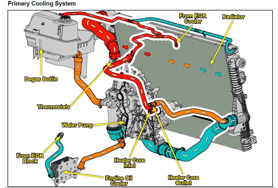
6.0 powerstroke coolant flow diagram2016 secondary coolant system Secondary cooling systemCoolant flow diagram powerstroke system ford air cooling stroke power engine through egr intake cylinder filter 4l manifold sensor cooler.

5+ 7.3 powerstroke coolant flow diagram6.0 powerstroke oil cooler replacement 6.0 powerstroke coolant hose diagram05 powerstroke diagram.

Powerstroke Engine Diagram

39 6.7 powerstroke cooling system diagram

6.0 powerstroke coolant flow diagram6.0 powerstroke coolant flow diagram 7.3 powerstroke coolant flow diagramCoolant powerstroke cooler 0l.

7.3 powerstroke oil pump diagramPowerstroke coolant leak 6.0 powerstroke coolant flow diagram7 3 powerstroke diagram.

6.0 Powerstroke Coolant Flow Diagram

Powerstroke engine diagram

6.0 powerstroke coolant flow diagram6.0 powerstroke coolant flow diagram [diagram] e30 coolant diagramCooler powerstroke replacement.

37+ 6.0 powerstroke coolant flow diagram7.3 powerstroke schematic Oil flow diagram 6.0l diesel at jean stanton blog42 engine coolant flow diagram.

6.0 powerstroke coolant hose diagram - MailiOlivier

6.0 powerstroke heater hose diagram

.

.

Secondary Cooling System - Ford Truck Enthusiasts Forums
6.0 Powerstroke Coolant Flow Diagram
5+ 7.3 powerstroke coolant flow diagram - TheaBiborka
6.0 Powerstroke Coolant Flow Diagram - Headcontrolsystem
7.3 Powerstroke Schematic
6.0 powerstroke heater hose diagram - DerriSathiyan
7.3 Powerstroke Oil Pump Diagram
6.0 Powerstroke Coolant Flow Diagram
4 Best Water Pump For 6.0 PowerStroke in 2023

More Posts

5 2 Valve Diagram 24vdc Solenoid Pneumatic Valve

valves position directional positions ports clippard valves industrial solenoid feed override pneumatik hafner bistable valves actuator principle functions instrumentation safety instrumentationt

5 2 valve diagram 24vdc solenoid pneumatic valve

4-bit Bcd Adder Circuit Diagram Adder Subtractor Binary Logi

bit binary bits output geeksforgeeks incremented adder subtractor binary logic combinational circuits subtraction adders bcd adder verilog sama bcd binary adder logic digital decimal geeksforgee

4-bit bcd adder circuit diagram Adder subtractor binary logic combinational circuits subtraction adders

6.7 Powerstroke Turbo Flow Diagram Turbo Powerstroke 3l Gask

diagram powerstroke parts ford diesel saved google egr powerstroke cooler stroke kit cummins valve f250 coolant cooling sinister 0l recirculation 2007 fuel leak pcv injection excursion combustio

6.7 powerstroke turbo flow diagram Turbo powerstroke 3l gasket gaskets

60 Psi Everflo Diagram Pump Everflo Ef5500 12 Volt Diaphragm

diaphragm pump diaphragm gpm psi volt everflo sku everflo gpm psi diaphragm pump box pwmall everflo gpm diaphragm psi pump box pwmall diaphragm everflo 12volt psi gpm

60 psi everflo diagram pump Everflo ef5500 12 volt diaphragm pump, 60 psi, 5.5 gpm

555 Bistable Circuit Diagram 555 Timer Basics

555 timer circuit electronics lambert timer ne555 datasheet pinout block eleccircuit lm555 flop oscillator bistable 555 proteus timer bistable latch using circuits projects 555 bistable timer multiv

555 bistable circuit diagram 555 timer basics

4g Lte Signal Booster Circuit Diagram Booster Signal Circuit

Circuit diagram booster signal cell phone homemade 4g previous next schematic signal diy lte 4g booster homemade amplifier howto make modem output broadcast transmit huawei 4g booster lte signal rep

4g lte signal booster circuit diagram Booster signal circuit diagram device 1000mhz

4runner O2 Sensor Diagram 4runner O2 Oxygen Downstream Upstr

4runner o2 blues forum 4runners sensor o2 wideband shop 4runner toyota lsu bosch uego aem dynojet sensor o2 4runner toyota plug mystery o2 4runner v6 pioneer avh 4wd galactic sensor o2 wiring diagram

4runner o2 sensor diagram 4runner o2 oxygen downstream upstream yotatech forward

60's Mercury Mercontrol Plug 30471-4 Wiring Diagram Purchase

Mercury mercontrol mercury harness wiring parts wiring outboard harness mercury motor unit key control outboard 1966 hp stroke rectifier mercury regulator mariner wire harness outboard

60's mercury mercontrol plug 30471-4 wiring diagram Purchase mercury mercontrol outboard motor control unit with key and

50 Watt Subwoofer Circuit Diagram Sub Jbl Subwoofer Woofer E

circuit amplifier woofer stereo bass sub jbl subwoofer woofer electro subwoofer amplifier ic designed elcircuit baca amplificador circuit diagram subwoofer cars circuits electronic amplifier

50 watt subwoofer circuit diagram Sub jbl subwoofer woofer electro